manufacturer of iris filter waveguide WR28(horn arraies, couplers, choke flanges, circulators)! supplier of WR28 (switchs, terminations, twists, multiplexers,combiners, dividers, isolators) components!
Precision Ka‑Band WR‑28 Waveguide Components – Custom Built for Your Applicatio
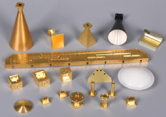
As a specialist manufacturer of Ka‑band WR‑28 (26.5–40 GHz) waveguide components, we machine each part strictly to customer drawings. Unlike higher millimeter‑wave bands, WR‑28 offers a balanced combination of moderate tolerances (typically ±5 μm to ±10 μm) and robust power handling, making it ideal for satellite equipment, communication links, phased‑array radar, and automotive radar – markets where reliability and repeatability matter as much as electrical performance.
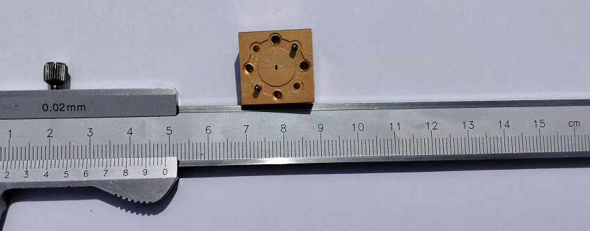
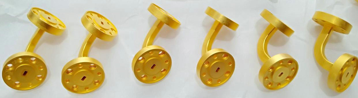
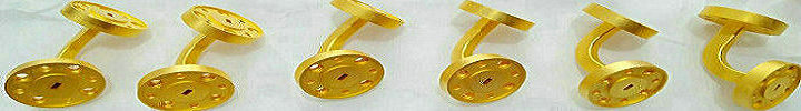
We are a trusted manufacturer of iris filter waveguide WR28, producing iris filters with window tolerances of ±5 μm to lock center frequency precisely. Our horn arrays are machined with flare angle and aperture tolerances of ±10 μm, delivering stable gain and controlled sidelobes. For couplers (directional and cross), we hold coupling hole positions within ±10 μm, ensuring directivity ≥20 dB. Choke flanges are cut with groove depth and width tolerances of ±5 μm for reliable high‑frequency sealing, while circulators feature Y‑junction cavity symmetry ≤5 μm to achieve isolation >20 dB across the full band.
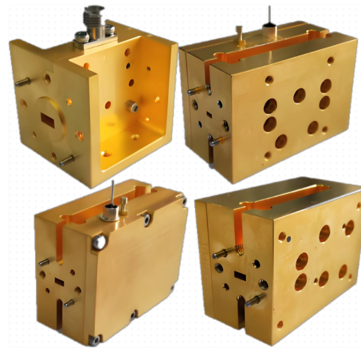
As a dependable supplier of WR28 components, we deliver electromechanical switches with rotor‑stator gaps ≤10 μm – critical for low insertion loss and high isolation in redundant satellite systems. Terminations are manufactured with absorber cavity tolerances of ±10 μm, holding VSWR ≤1.03:1. We produce twists with polarization rotation accuracy of ±0.5°, multiplexers with cavity dimension consistency of ±5 μm, and combiners, dividers, and isolators that meet strict amplitude balance (±0.5 dB) and phase consistency (±5°) requirements.
Our typical materials include aluminum (with gold or silver plating) for lightweight radar applications, as well as oxygen‑free copper for high‑power satellite links. We inspect every component using CMM and VNA up to 40 GHz. Send us your drawings – we will deliver WR‑28 waveguides machined exactly to your satellite, communication, radar, and automotive specifications.
Complete List of Ka-Band (WR28) Precision Machined Waveguide Components
| Component Category | components name | typical tolerances | |||||||
|---|---|---|---|---|---|---|---|---|---|
| Transmission Line | |||||||||
| Straight waveguide section | Inner bore tolerance ±5 μm, straightness >10 μm, surface roughness Ra ≤0.2 μm | ||||||||
| E-plane. H-plane bend | Bend radius and angle tolerance ±0.3°, internal matching step tolerance ±5 μm | ||||||||
| Twist | Polarization rotation accuracy ±0.5°, smooth inner wall transition, insertion loss ≤0.13 dB/inch | ||||||||
| power division and management. | |||||||||
| combiners, power dividers | Amplitude balance ±0.5 dB, phase consistency ±5°, high internal symmetry | ||||||||
| divider couplers | Coupling hole size and position ±10 μm, coupling flatness ≤±0.8 dB, directivity >20 dB | ||||||||
| cross couplers | coupling accuracy ±0.5 dB, high port‑to‑port isolation | ||||||||
| frequency selection & control. | |||||||||
| bandpass filter | Iris window tolerance ±5 μm (directly defines center frequency accuracy, e.g., passband 25–28 GHz, IL≤0.4 dB) | ||||||||
| Isolator | Ferrite pocket tolerance ±10 μm, low insertion loss (typ. ≤0.4 dB), high isolation (>20 dB) | ||||||||
| circulator | Y- junction cavity symmetry ≤5 μm, consistent isolation (20–25 dB) for all ports | ||||||||
| multiplexers, diplexers. | cavity dimension consistency ±5 μm, high channel‑to‑channel isolation and frequency selectivity | ||||||||
| Switch | rotorstator gap ≤10 μm, low insertion loss (typ. ≤0.15 dB), high isolation (>50 dB) | ||||||||
| Directional coupler | coupling hole diameter tolerance ±2 μm, directivity >22 dB | ||||||||
| signal transition & load | |||||||||
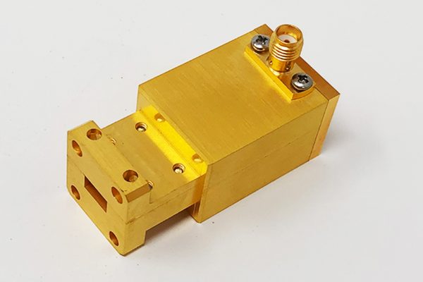
| Probe transition(waveguide‑to‑coax) | Probe dimensions and position ±10 μm, backshort depth tolerance ±10 μm | ||||||||
| termination (load) | absorber cavity tolerance ±10 μm, low VSWR (typ. ≤1.03:1) | ||||||||
| horn antenna | |||||||||
| flanges & sealing. | |||||||||
| Plain flange | Flatness ≤1.5 μm, dowel pin hole IT5 grade | ||||||||
| Choke flange | Ring groove depth tolerance ±1 μm | ||||||||
- home
- products
- contact
- equipments
- CNC waveguide components
- microwave components
- millimeterwave assemblies
- submillimeter products
- Terahertz (THz) systems
- waveguide rectangular
- D band waveguides
- Ka band waveguides
- V band waveguides
- E band waveguides
- W band waveguides
- G band waveguides
- Ku band waveguides