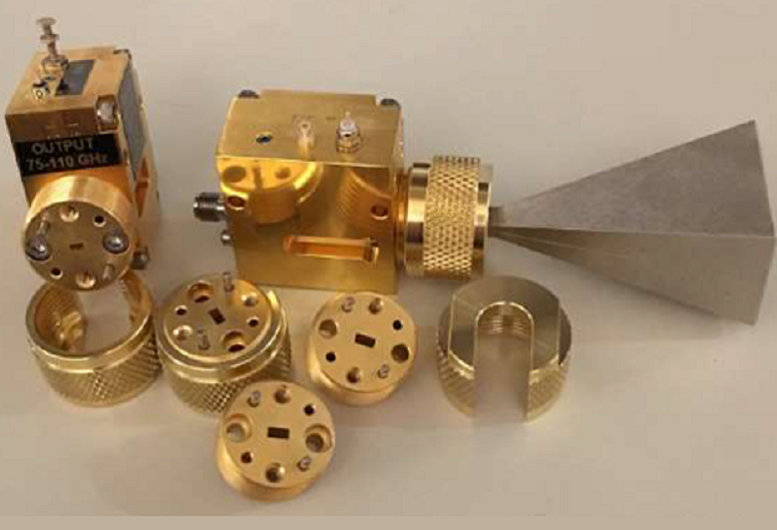
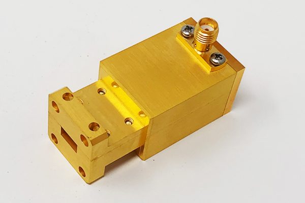
manufacturer of satellite millimeterwave components (straights, bends, twists, transitions)E band ! supplier of custom starlink waveguide (filters, couplers, attenuators, intracavities, feed horns,) and flanges!
we manufacture the Metal structures for starlink’s WR28 sWaveguide chains
We are a specialized contract manufacturer focusing on millimeter‑wave and sub‑millimeter‑wave metal components. We do not design complete RF devices, nor do we assemble entire systems. Instead, we machine waveguide cavities and structural parts exactly to customer drawings – and our customers include suppliers working on Starlink’s Ka‑band (WR28) links.
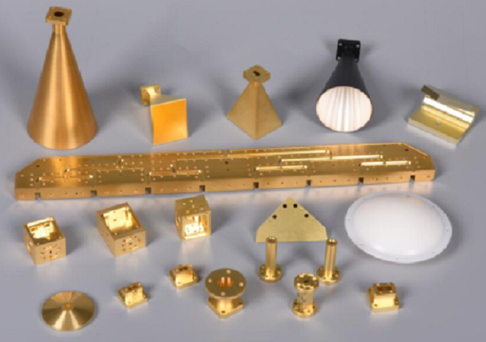
What do we make? The critical metal bodies of: Straight, bent, twisted, and transition waveguides. Iris filters, diplexers, and multiplexer cavities
,Circulator and isolator housings, Choke flanges, coupler bodies, and feed horn cavities. All these parts are made from 6061 aluminum (or other specified alloys), with inner surfaces plated in silver or gold. They are the “plumbing” that connects active RF chips to antennas – but we only supply the precision‑machined shells, never the ferrites, magnets, or semiconductor dies inside.
Why us? Because WR28 Ka‑band requires extreme accuracy: Dimensional tolerances: ±5–10 µm Surface finish: Ra < 0.2 µm (mirror‑like) Complex 3D features: E/H‑plane bends, 90° twists, thin iris windows, and λ/4 choke grooves.
typical WR28 waveguide chain – starlink satellite (Ka-band)
| Comp | Qty | L (mm) | IL (dB) | Material | |||||
|---|---|---|---|---|---|---|---|---|---|
| WR28→2.92mm Trans | 1 pc | 25 mm | 0.20 | dB 6061Al+Au | |||||
| Straight WG | 2 pcs | 30 mm, 20 mm | 0.02 dB ea | 6061Al+Ag | |||||
| Isolator | 1 pc | 15 mm | 0.30 dB | Ferrite | |||||
| Straight WG | 1 pc | 25 mm | 0.02 dB | 6061Al+Ag | |||||
| Circulator | 1 pc | 15 mm | 0.30 dB | Ferrite | |||||
| E‑plane 90° Bend | 2 pcs | – | 0.10 dB ea | 6061Al+Ag | |||||
| Straight WG | 2 pcs | 40 mm, 40 mm | 0.03 dB ea | 6061Al+Ag | |||||
| Iris Filter | 1 pc | 50 mm | 0.50 dB | 6061Al+Ag | |||||
| Straight WG | 1 pc | 25 mm | 0.02 dB | 6061Al+Ag | |||||
| 90° Twist | 1 pc | 60 mm | 0.10 dB | 6061Al+Ag | |||||
| Diplexer (Tx/Rx) | 1 pc | 80 mm | 0.50 dB | 6061Al+Ag | |||||
| Straight WG | 1 pc | 50 mm | 0.05 dB | 6061Al+Ag | |||||
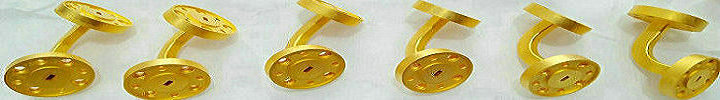
| Choke Flange | 1 pc | 10 mm | 0.05 dB | 6061Al+Ag | |||||
| Feed Horn | 1 pc | 70 mm | 0.10 dB | 6061Al+Ag | |||||
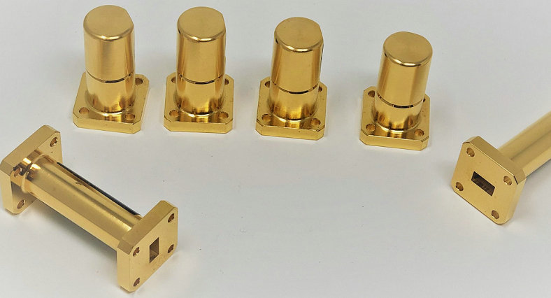
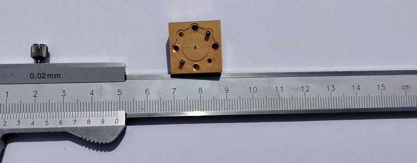
starlink straight waveguides (WR28),most basic and most commonly used.
| parameter | value | unit | condition | ||||||
|---|---|---|---|---|---|---|---|---|---|
| Waveguide Size | WR28 (WG22 / R320) | — | MIL-DTL-85H | ||||||
| Frequency Range | 26.5 – 40.0 | GHz | Full band | ||||||
| Cutoff Frequency (TE10) | 21.08 | GHz | Theoretical | ||||||
| Inner Width (a) | 7.112 ±0.005 | mm | Broad wall | ||||||
| Inner Height (b) | 3.556 ±0.005 | mm | Narrow wall | ||||||
| Wall Thickness | 1.0 – 1.5 | mm | Standard | ||||||
| Material | 6061-T6 Aluminum | — | Aerospace grade | ||||||
| Inner Coating | Silver (Ag) | — | Electroless + electroplated | ||||||
| Coating Thickness | 5 – 10 | um | On inner surface | ||||||
| Surface Roughness (inner) | Ra ≤ 0.2 | um | After plating | ||||||
| Length (standard) | 25, 50, 100, 150, 200 | mm | Custom lengths available | ||||||
| Length Tolerance | ±0.05 | mm | For critical phase-matched pairs | ||||||
| Flange Type | UG-599/U (cover flange) | — | MIL-F-3922 | ||||||
| Flange Hole Pattern | 4 holes, Ø3.6 mm on 21.1 mm circle | — | Square pattern | ||||||
| Insertion Loss | ≤0.05 | dB/100mm | @ 30 GHz, silver plated | ||||||
| VSWR | ≤1.05:1 | — | straight section with flanges | ||||||
| Power Handling (CW) | 1.5 – 2.0 | kW | @ sea level, matched load | ||||||
| Power Handling (space) | 0.5 – 1.0 | kW | @ vacuum, no convection | ||||||
| Phase Length Tolerance | ±1.0 | degree/100mm | @ 30 GHz for matched pairs | ||||||
| Mass | 8 – 12 | g/100mm | Aluminum, with flanges | ||||||
| Leakage (RF) | ≤ -100 | dBc | With choke flange or gasket | ||||||
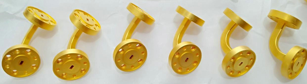
waveguide bends used in satellite (Ka-band, WR28) millimeterwave parts
| parameter | value | application in Starlink (WR28, 26.5–40 GHz) | |||||||
|---|---|---|---|---|---|---|---|---|---|
| Waveguide type | WR28 (rectangular) | Satellite feeder link (Gateway ↔ Satellite) | |||||||
| Frequency range | 27.5 – 30.0 GHz (Tx) / 17.7 – 20.2 GHz (Rx) | Tx/Rx separate paths | |||||||
| Bend types used | E‑plane bend, H‑plane bend, Miter bend (90°), Smooth bend | Routing around thrusters, batteries, star trackers | |||||||
| Typical bend angle | 90° (most common), 45°, 60°, 180° | 90° used in 80% of satellite internal layouts | |||||||
| Bend radius (E‑/H‑plane smooth) | 15 mm – 25 mm (≥ 2× waveguide width) | Compromise between low loss and compactness | |||||||
| Insertion loss per 90° bend | 0.05 – 0.10 dB (smooth bend) | Budget: <0.5 dB for all bends per satellite | |||||||
| Return loss (VSWR) | < 23 dB (VSWR <1.15) | Maintained across full Ka-band | |||||||
| Number of bends | per satellite 4 – 8 pieces | Average ~6 bends per Ka‑band payload | |||||||
| Total loss contribution | 0.3 – 0.5 dB (all bends combined) | Within link margin (typical fade margin 3–5 dB) | |||||||
| Surface finish | Inner wall: Silver plating (5–10 µm) | Improves conductivity (skin depth ~1.3 µm at 30 GHz) | |||||||
| Manufacturing tolerance | ±10 um on inner dimensions | 5‑axis CNC milling | |||||||
| Power handling (CW) | 50 – 100 W | (with silver plating) Well above typical satellite Tx power (5–20 W) | |||||||
We achieve this with 5‑axis CNC machining centers, complemented by EDM and precision lapping where needed. Every cavity is cut from solid 6061Al, then plated. No casting, no 3D printing – only subtractive manufacturing that meets space‑grade reliability.
To be clear: we do not design the filter, the diplexer, or the horn. We simply read your drawing, choose the right toolpath, and deliver a metal cavity that fits your electrical design perfectly. If you need millimeter‑wave waveguide structures made exactly to your specs – without design work, without unwanted extras – we are your shop. Send us your WR28 (or even higher) drawings, and we will machine them.
- home
- products
- contact
- equipments
- CNC waveguide components
- microwave components
- millimeterwave assemblies
- submillimeter products
- Terahertz (THz) systems
- waveguide rectangular
- D band waveguides
- Ka band waveguides
- V band waveguides
- E band waveguides
- W band waveguides
- G band waveguides
- Ku band waveguides