
YDTech® manufacturer of drive dog(top) pins, changeable parts on face drive heads, for movable center chucks! supplier of changeable pins for face driving dead chucks, grinding, gear cutting, turning, millingg in china.
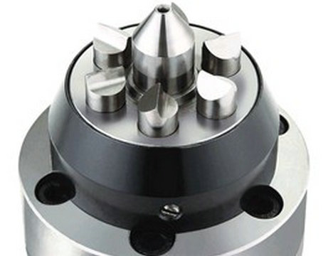
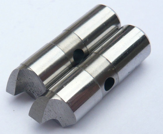
locking a face drive on a self-centering chuck involves a few steps, and the specific process may vary depending on the make and model of your equipment. ensure that the face drive is properly aligned with the center of the chuck and that the jaws of the chuck are open and positioned to grip the workpiece. insert the center pin of the face drive into the center hole of the chuck, making sure that it is securely seated and aligned. we only produce drive pins, needle roller pins,precision hardened parts,etc. custom your drawings or samples. not face driver.
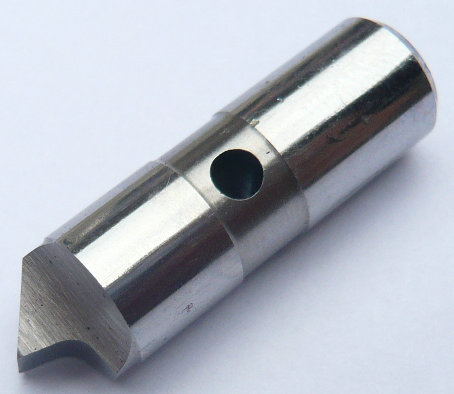
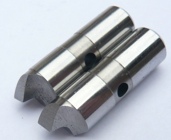
test the grip and alignment of the workpiece by rotating the chuck by hand or at low speed, checking for any wobbling or slipping. Make any necessary adjustments to the grip or alignment of the workpiece or face drive as needed. it is important to follow the manufacturer's instructions and guidelines for your specific equipment when using a face drive with a self-centering chuck to ensure safe and effective operation.
with a mechanical tailstock, the average tightening with one hand exerts sufficient force to build up about 1,700 pounds of pressure. on a power-operated tailstock, force equals the area of the piston in square inches times the input pressure into the cylinder in pounds per square inch.
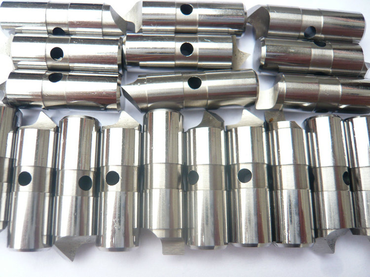
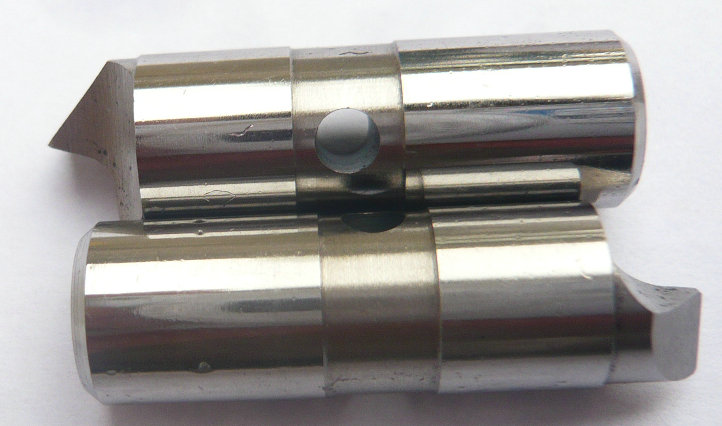
position the jaws of the face drive around the outer diameter of the workpiece and tighten them using the appropriate wrenches or tools. Make sure that the jaws are tightened evenly to ensure a secure grip on the workpiece. use the chuck key or other locking mechanism on your self-centering chuck to lock the jaws in place, ensuring that they remain securely tightened around the workpiece.
drive pins and center pins of special design for various work piece surfaces and clamping conditions we design and manufacture a variety of drive pins and center pins of special design.
FDP-5 standard of drive pins,face drivers, lathe face driver driving pins,sizes of drive pins, changeable driving pins, drive teeth pins
| face drive pins (diameter) | CNC driving pins (length) | lathe drive teeth pins (depth) | driver pin teeths (width) | drive pins technologies | |||||||
|---|---|---|---|---|---|---|---|---|---|---|---|
| 0.800 | 3.622 | 1.732 | 0.183 | FDPT 2023DD | |||||||
| 0.800 | 3.622 | 1.722 | 0.214 | FDPT 2023DD | |||||||
| 0.800 | 3.622 | 1.813 | 0.228 | FDPT 2023G | |||||||
| 0.800 | 3.622 | 1.823 | 0.258 | FDPT 2023VVD | |||||||
| 0.800 | 3.622 | 1.865 | 0.288 | FDPT 2023G | |||||||
| 0.800 | 3.622 | 1.965 | 0.265 | FDPT 2023G | |||||||
| 0.800 | 3.622 | 1.988 | 0.248 | FDPT 2023V | |||||||
| 0.800 | 3.622 | 2.008 | 0.358 | FDPT 2023HU | |||||||
| 0.800 | 3.622 | 2.156 | 0.368 | FDPT 2023YH | |||||||
| 0.800 | 3.622 | 2.168 | 0.387 | FDPT 2023JJ | |||||||
| 0.800 | 3.622 | 2.225 | .281 | FDPT 2023T | |||||||
| 0.800 | 3.622 | 2.254 | 0.402 | FDPT 2023H | |||||||
| 0.800 | 3.622 | 2.287 | 0.442 | FDPT 2023HH | |||||||
| 0.800 | 3.622 | 2.345 | 0.462 | FDPT 2023TG | |||||||
| 0.800 | 3.622 | 2.369 | 0.482 | FDPT 2023G | |||||||
| 0.800 | 3.622 | 2.465 | 0.520 | FDPT 2023T | |||||||
| 0.800 | 3.622 | 2.485 | 0.542 | FDPT 2023GT | |||||||
| 0.800 | 3.622 | 2.546 | 0.562 | FDPT 2023T | |||||||
| 0.800 | 3.622 | 2.548 | 0.586 | FDPT 2023GT | |||||||
| 0.800 | 3.622 | 2.559 | 0.602 | FDPT 2023G | |||||||
| stainless steel drive pins, face driver CNC drive pins, changeable pins, lathe deep face drivers, face driver technologies | |||||||||||
the first cut should generally be towards the face driver to better set the workpiece and allow the drive pins to do their work by biting into it. once the first cut is made towards the face driver, then cuts toward the tailstock can be made. grinding and hard turning.
a face driver has two main components, the drive head and the mounting. the mounting locates the driver in the machine with either a morse taper shank mount directly into the machine taper; or a chuck mount chucked between special chuck jaws; or a flange mount bolted to a spindle adapter on the machine spindle. the illustration shows a morse taper shank. the drive head contains the compensating medium ; which allows the pins to adjust to variations in the locating face and the spring-loaded center point.
- home
- products
- contact
- equipments
- face driver pins
- drivers vs pins
- S7 drive pins
- lathe drive pins
- mechanical drive pins
- hardened drive pins
- CNC face drivers
- drive fixture pins
- changeable driving pins
- face driver parts
- drive pins
- face drives
- drive chuck
- hardened pins
- drive shafts
- center pins
- drive claws
- drive grips
- drive chuck
- driver tops
- locating pins
- driving pins
- cylindrical rollers
- needle rollers
- dowel pins
- capillary tubes